A lack of reviewers can lead to more polarized review outcomes

I recently was part of a manuscript review where the editors had to invite 12 reviewers to finally get 3 of them to agree to review, over a two-and-a-half-month process. This got me thinking about what kind of sample the remaining 3 reviewers that accepted the review represented.

The basic idea is quite simple: If there is a subset of reviewers that are more likely to accept a review than the population average, then a larger fraction of papers will end up in the hands of those reviewers. One can imagine scenarios where such subsets are not who we’d hope to have as reviewers, especially in fields with disagreements between groups of scientists. Broadly speaking, fields where it is customary to formally ask to exclude a few reviewers should fall into this category.

My specific assumptions here might be off for any individual case, but the basic principle of this example should hold regardless: Let’s assume that the probability of accepting a review invite is 40%, and the latency to reply to an invite is 1-20 days. Now as an editor, assume that if you aren’t waiting for more than 5 people to reply, and you haven’t heard back from anyone in a week, you invite more reviewers, until you have 3. In this simplified model it takes ~60 days for 98% of papers to find 3 reviewers (Fig. 1a).

Now let’s assume that some percentage, say 20% of potential reviewers have biases about a topic or author, one way or another. The likelihood of ending up with 2 out of 3 reviewers having biases, and taking over the review process, is around 10% (Fig. 1b) – since this probability is low we’ll call this a more or less functioning review system.

However, it seems reasonable to assume that the probability of accepting a review, and the latency to reply, depends to some extent on how a reviewer feels about the manuscript or authors. So what happens if reviewers become less available, in this scenario? If we reduce the probabilities of disinterested reviewers accepting a review invite a bit to 30% (which seems in line with people’s experience in systems neuroscience in 2022), and 80% for a subgroup that feels strongly about the topic, and the delay for replying to up to 30 or up to 5 days respectively, the system breaks down a bit: Reviews now have a high chance of bouncing around the system until they hit reviewers from the subgroup that are more likely to accept the review. With the above assumptions, the likelihood of getting reviewed by 2 out of 3 reviewers from the more biased subgroup jumps from 10% to almost 50% (Fig. 1c). Even if there’s only 10% of strongly opinionated reviewers in the field, the probability of having one such reviewer is now ~60%.

Fig.1 a: Cumulative probability of how long it takes to find 3 reviewers under the two scenarios. b: Probability of having 1,2, or 3 reviewers come from a small pool of reviewers, if everyone reviews at the same rate. c: If a small (possibly biased) pool reviews some papers at 80% and replies in 1-5 days, vs. a baseline rate of 30% and 1-30 days, that small pool of reviewers ends up controlling a high number of review processes.


What this example means is that if some of these dynamics apply to the real world, we should expect reviews to be significantly more polarized than the opinions we might get by e.g. talking to people at a meeting. It also means that it is much easier for a subset of people to assume an outsized level of control of a field, be it by holding back out-group papers, and/or accepting in-group ones. The assumption of an 80% review rate for the subgroup might be unrealistic, but would only have to apply for a subset of manuscripts in order to exert significant control over a field.

Now what could be done to improve the robustness of peer-review? There are a few proposals that have been increasingly discussed recently. First, this calculation would not apply if reviewers recused themselves from reviewing papers in which they are biased, or if the likelihood of accepting a review was the same across a full sample of experts – which would require that unbiased reviewers have the time and willingness to review, including outside their immediate fields. Paying reviewers a fair consulting fee might increase the availability of reviewers and de-bias the pool.

More fundamentally, there is the question of why scientific reviews are polarized in the first case and why it is, for example, customary in some fields to exclude reviewers. Proposals here include separating the review for scientific soundness from the determination of whether a manuscript is deserving of specific journal labels (which bestow future funding and career opportunities unrelated to the work itself), reducing the weight of journal labels on the perceived quality of the work, moving discussions of the worth of a result into a publicly accessible forum, for example after a manuscript is posted as a pre-print, or by publishing the reviews after the fact, as is done for example by eLife.

Posted in Doing science | Comments Off on A lack of reviewers can lead to more polarized review outcomes

Basic techniques for making mechanical structures for systems neuroscience

In systems neuroscience, a lot of times we need to build or modify mechanical support structures to keep devices in place. This could be cameras, electrode manipulators, slides, lenses, headposts, etc. Almost universally, these structures need to keep relatively light devices or preparations at precise positions, this means they should not drift, vibrate, or deflect.

This is an extremely large topic and I am only going to cover some basic but concrete points here with the goal of clearing up some common misconceptions and providing some basis for making better design or purchasing decisions. Keep in mind that in a lot of cases it may be advisable to pay an expert to help design your rig or to look for existing solutions. Your time is expensive, and spending it to build something that you could buy is often a bad trade-off.

A lot of the more fundamental points in this post are made better by Dan Gelbart in his excellent video series ‘Building Prototypes’. If you have the time, watch these.

Stiffness vs. yield strength

People often spend their efforts in the wrong place when building instruments because they think that in order to reduce drift or vibration, the things they build need to just be ‘as strong as possible’, which means that the best structure would be the one that can hold the most weight. This is usually a misconception because what matters when building  instruments is stiffness at low stress/strain, not strength.

The above figure shows a strain (deformation) vs. stress diagram for some material. The terms are a bit unintuitive, but in the context of thinking about the stiffness of a structure, this translates to the relationship between an applied force (stress, y-axis) in something like newtons (handwavy:  1 N ∼100 g) and the resulting deformation (strain, x-axis) in mm or μm.  There are two major properties of any structure to consider:

  • The yield strength (red region): This is the stress/strain at which the structure begins to permanently deform and fail. This point is important for building airplanes but almost completely irrelevant for building instruments.
  • The elastic stiffness (black region): Think of stiffness as the linear deflection per unit of force applied, even for small forces where the structure springs back as soon as the force is removed. This is the metric that matters for us when building things in the lab because it governs how much (and what what frequency) structures vibrate, or move in practical use when you’re not leaning on them.

What you usually want is to have a steep slope / high stiffness, regardless of what happens in the red region, because we’ll never get there. To really make this point clear, here’s an example, stolen straight from Dan Gelbart’s videos. I’m measuring the deflection of a single 80/20 rail, supported on both ends, with a weight of about 1kg or so placed in the middle.


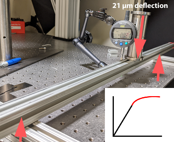
This beam is pretty strong, certainly impossible (for me) to break by hand, and we’re getting a deflection of around 20 micron.

Now instead of the single uninterrupted beam, lets put two beams, only held together with rubber bands. I can push down on this with my hand and break it pretty easily.

However, we get only about half the deflection from the weight, because even though the yield strength of this rubber banded beam is quite pathetic, as long as the two pieces keep touching, its stiffness is the same as a single piece of twice the thickness. This means that the slope in the elastic linear bottom portion of the strain vs stress curve is higher, and the beam is stiffer. This means that this insane looking rubber band contraption would really be twice as good at holding up a microscope slide than the ‘stronger’ uninterrupted beam, as long as the rubber bands stay in place.

Some other examples of the same principle:

  • Attaching a piece of equipment to a structure with a spring loaded clamp is as stable as using a bunch of M6 bolts (until you bump it with an elbow of course).
  • ‘Properly’ tightening screws the way you would on a bike or car is almost always unnecessary.
  • Using adhesives, even on questionably suitable surfaces such as smooth metal, is often equivalent to screws (not in terms of serviceability of course, and only is the glue film is very thin, and stiff).
  • For an optical post base, or anything screwed into a breadboard, if the base is flat and in contact with the table already, adding more screws/clamps is not going to do anything. This is why clamping forks work.

It is important to consider where stiffness is needed and where not. In the following, we will assume that stability under light loads is important, as for example in an electrophysiology setup or a microscope. In many applications, this is not the case and e.g. a camera for rough behavior tracking, mounted on a plastic bracket held in place with epoxy is perfectly functional even if the plastic deforms a bit if you move the camera’s usb cable.

Everything deflects and vibrates

As the above example shows, even a pretty light weight is enough to bend a 1″ rail enough to destroy any recording or optical measurement we encounter in neuroscience. Different applications  have vastly different tolerances, but in almost all cases it is useful to remember that anything, whether it’s a piece of paper or a thick bar of steel, stereotax arms, manipulators, your microscope, tables, the floor in your room, etc. all bend in the same way as soon as any force is applied. The only question is by how much. This is why air tables have to be extremely thick to stay flat. The trick is to have things not bend too much, by putting material where it best resists the deformation that would cause issues.

An important baseline assumption to keep in mind here is that rooms, tables (even optical tables) are always moving / vibrating a little bit. This means that even in the absence of explicit forces, structures like to move around at their resonant frequency, and it is therefore often important to make stiff structures even if you do not expect dynamic loads. This mostly matters for microscopes and for electrophysiology.

Material matters, but not as much as you might think

The stiffness of materials (the slope of stress vs. strain in the above diagram) is termed Young’s modulus. Forgetting about the exact definition of the units, here’s some approximate examples to give us a sense of relative scale (all in GPa):

Acrylic/Epoxy: 3
Wood: 5-10
Aluminum: 70 (Easy to work with, cheap, does not corrode easily)
Titanium: 100 (The downsides of aluminum and of steel, at an even higher price)
Steel: 200 (Hard to work with, expensive, corrodes unless you get even more expensive and harder to work with stainless)

Practically, this means that a structure made from steel is about twice as stiff as the same one made from aluminum. However, as we’ll see, changes in the mechanical design of parts can easily yield changes of an order of magnitude and can easily offset this disadvantage.

Compared to metals, plastic is going to deform like crazy under load. Properly designed plastic parts can of course achieve precision, and 3d printing is nice, but largely plastics are in a huge disadvantage.

Aluminum is your friend

Aluminum, while half as stiff as steel, is also about half as heavy, and usually less than half as expensive to build with. This means that you can compensate by making an aluminum structure twice as thick/wide/deep as a steel one for the same weight, save money, and get a higher performance end result. The structural frames in some of the highest precision CNC machines in the world are made from aluminum, so it’s likely good enough for us as well.

The other incredible upside of aluminum is that it can be modified quite easily with hand tools in a lab setting. Working with aluminum is almost as as easy as working with wood, plus you can cut threads. This can help you solve problems extremely quickly and cheaply if you have a place to put a vise and you’re comfortable making some metal chips:

  1. Get a decent hacksaw, and a file.  You can now cut construction rails to length, or quickly cut basic shapes out of aluminum sheets.
  2. Get a cheap drill press, or a hand drill, and a decent set of drill bits (a spotting bit which does not wander around when starting holes is nice to have, as well as chamfer bits to make the edges of holes nicer). Drilling holes in aluminum is easy and fast.

You can now make parts that should solve at least half of your basic construction needs in the lab setting so fast that if can sometimes outperform buying them.

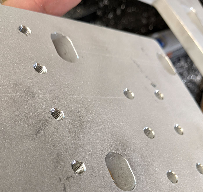
Bracket made from extremely cheap aluminum stock, entirely by hand in <10 minutes. Works as well as an expensive commercial one, which would have taken similarly long to fill in an order for. Fun side question: why are the 2 bolts enough?

3.  Get an M6 and M3 tap and a handle (here for example) and learn how to tap holes. You can now make parts that attach to each other without using nuts, and parts that can act as ‘breadboards’ to mount other stuff to. Use M6 wherever you can (these are easy to tap and hard to break), and M3 for small stuff (careful with the tap though, these snap easily).

Tapped M6 holes in a waterjet cut piece of aluminum make extremely versatile parts.

Use 80/20 rails (or equivalent)

80/20 rail (generic name is ‘T-slotted construction rail’) is just amazing. These are extruded aluminum beams with a profile that allow the addition of screws anywhere along their length with the help of special captive T-nuts. Using 80/20 is a whole topic, and its useful to look at some examples to get a sense of what can be done.

You can quickly make enclosures, tables, microscope stands, optical setups, cable management out of this stuff. It’s kind of cheap, and fast. If you keep a few lengths around, plus some brackets and screws, a hacksaw and a drill, you can fix issues that come up in your rig in very short order.

Pro tips:

  • At least in the US, 1-2 inch based rail is cheapest, and works just fine with M6 based T-nuts. If you mix 1/4-20 and M6 screws it is a great idea to make it a rule that there can, for example, only be black 1/4-20 nuts and  silver M6 ones in your workspace.
  • As outlined above, you can make brackets to connect multiple of these rails out of 1/4″ aluminum stock with a drill, or buy commercial ones. Often, using flat 1/4″ plates is more versatile than using expensive 90degree inside braces.
  • Use the fact that the T-nuts can be repositioned freely to your advantage, for example think about what dimension might need to change later and align the brackets accordingly.
  • The central opening (there’s one in the single-width ones, 2 or 4 in larger ones) in these extrusions is just about perfect to cut an M6 thread in, allowing us to attach adapter brackets or whatever at the end of rails.
  • If your structure closes off both ends of a rail so you can’t later add captive nuts, it can be a good idea to leave an extra one or two sitting in there so if you need to attach something later you can use them, or have a few (more expensive) drop-in nuts at hand for such cases.

Geometry matters

Because we are often building things from beams, straight lines and triangles are good, and any other shapes are usually bad.

(Source: sparkfun)

As a simple example, here is a simulation of a 1.5m high Thorlabs 95mm beam, mounted on a base, with a 10N side load. We get 71 μm of deflection. Adding a simple brace, made from a piece of 1″ 80/20 rail and a bracket cuts this down to 1 μm. When in doubt about the stability of something, try adding braces that directly lead from the load to a fixed point. If you used 80/20 rail this should be extremely easy.

Waterjet cutting gets you extremely far

If you get to a point where 80/20 does not fit, waterjet cutting is a quite economical way to make one-off shapes out of aluminum (or other material) sheets. It it a great way to make complicated custom pieces from metal at a fraction of the cost or complication of CNC machining. Again, there’s a dedicated Dan Gelbart video about this. I like to order from big blue saw in the US because they quote immediately and stock a lot of material thicknesses, but just about any vendor should do.

As an unrealistic toy example, imagine you need to hold something 30cm above an optical table and have it be stable under some side load, let’s say a micromanipulator that is not allowed to vibrate. Let’s compare a Thorlabs 1.5″ steel post (~$100, 1-2 days wait time) and a waterjet cut (0.5″ thick) aluminum plate (~$150, 30 min design time, 1 week wait time), mounting holes, a pair of 90 degree brackets for mounting on table, etc. not shown here:

With a 10N load, the 1.5″ steel post deflects by 40 μm, the aluminium plate by 0.2 μm. That’s 200x stiffer, plus you can put whatever custom threaded holes etc. for basically the same price, at the cost of being a less modular solution.  This is of course an unfair comparison because of the advantageous geometry of the custom plate (and the lead time is higher), but that is exactly why waterjet cut parts are great: you can easily get the geometry that works best.

Waterjet cutting also allows you to very easily add through- or tapped holes at specified locations: Just order the part with undersized ‘pilot holes’ cut with the waterjet and then finish (and optionally tap) them by hand.

Custom designed breadboard for a microscope made from 0.5″ aluminum, straight from the cutter. All the pilot holes were waterjet cut to a bit under 5 mm diameter (they come out of the waterjet cutter tapered and uneven), and will be hand-drilled to either an M6 clearance (6.5 mm should do) or tapped to a M6 thread (drilled to ~5.25 mm and then tapped).

Should you?: In building (mostly one-time use) scientific experiments, the most expensive line item is often your time. If you can solve the problem by spending a few extra bucks on thorlabs or other commercial-off-the-shelf parts, or screw together some ugly 80/20 and get going with your experiment, do that. Making custom waterjet or CNC parts, or messing around with 3d printing, is for cases where you need to go beyond existing solutions, and for those cases only.

How to: Start by making your part drawing, and export it as DXF file. Almost any software will do, but it helps if you can enter measurements, and proper CAD tools like any of the autodesk offerings, or solidworks are ideal, but you can get pretty far using illustrator or similar tools. Measure twice, order once, and when in doubt, add a few extra pilot holes in places where you might need to attach something. When you get the part, fix the mistakes you made in your initial drawing with your hacksaw and file.

Keep in mind that waterjet cut pieces will not be guaranteed to be flat to amazing tolerances, and the cut edges will all be tapered from the water jet expanding towards the bottom. If you need the part to be flat, you might need to buy a proper breadboard, or get your plate surface ground at a machine shop. However, for many lab applications, flatness is pretty irrelevant because components of the experiment will usually be individually positioned with regard to each other or some other reference.

Posted in Technical things | Comments Off on Basic techniques for making mechanical structures for systems neuroscience

Review: Hot glue

This is part of a series in which I review various glues etc. (Epoxy, Superglue). Today we’re looking at an arts and crafts favorite: Hot glue.

Hot glue is surprisingly useful for quickly building large, temporary, non-precise structures and tacking things in place.

Basic properties:

  • It can be useful to think of hot glue as an adhesive filler, rather than as a glue. This stuff is good to keep things roughly in one place, and fill gaps. I use this a lot to keep wires/switches in place inside enclosures, for example. For anything beyond that, other glues (usually epoxy) are better suited.
  • Bonds to a lot of materials, like plastics or wood, but bond depends on temperature. Usually performs quite poorly on metals.
  • Can fill gaps, and can be built up into layers pretty quickly. Can for instance be used to make nice fillets in glued plastic cases. Keep in mind though that ethanol will break the adhesion on hot glue eventually, so this is not the best choice for boxes that need to be cleaned often. It is also practically impossible to make thin layers of this stuff because it hardens as soon as it thins out between two surfaces.
  • Remains flexible/rubbery – look at the un-melted glue sticks, that’s exactly what the glue joint ends up as. This makes hot glue pretty much completely unsuited for any joints that require stiffness.
  • Best use cases are making temporary enclosures out of plastic or wood, or tacking things in place, like for instance wires, switches, etc.

Pro tips:

  • You will eventually burn yourself on this stuff.
  • Forms thin strands, so don’t use in locations where you don’t want strands of this stuff floating around.
  • A can of keyboard cleaner (whatever refrigerant they use these days) held upside down can be used to quickly cool the surface of a glob of hot glue and set it quickly. This will however deposit a lot of the bitter additives they put into the refrigerant, and this stuff is not great in terms of literally dispersing greenhouse gas.
  • To remove hot glue, ethanol/acetone can be used.
  • To make pretty well performing hacky brackets or mounts in a pinch you can attach a piece of equipment with hot glue, build up a well shaped support structure (possibly shaping it with a razorblade), and then cover it with epoxy to form a better structural layer. If done well, this approach can be used to very quickly make mechanically decent structures for quick rigs at summer schools etc.
  • With some practice, a covering of hot glue on a cable can make odd looking but decent strain relief.
  • If you need maximum adhesion, it’s worth it getting good quality glue sticks, so consider not just getting whatever is cheapest. Steinel has been recommended, but there is a whole world of options out there.

How to use:

  • Give enough time to pre-heat the gun. barely melted hot glue does not adhere well.
  • As always, consider cleaning the surfaces if you need maximal adhesion.
  • Apply the glue.
  • Do not touch until you are sure the glue has cooled, unless you like dragging thin strands of the stuff across the lab.

What to buy:

  • Get a decent hot glue gun that heats up quickly, the whole point of this stuff is speed.
  • Avoid small glue guns, a main application area for hot glue is large glue joints.

Rating: ⭐⭐⭐⬜⬜


Posted in Technical things | Comments Off on Review: Hot glue

Review: Superglue

This is the second part of a series (I did epoxy before) in which I will review various glues etc.
Superglue / cyanoacrylate is a staple in almost all neuroscience labs. While there are some applications for super glue, in the lab setting there are usually better glues for the job.

Basic properties:

  • Thin films can cure very rapidly, this is the main advantage of superglue, but one that is not often needed in lab.
  • Not great at filling gaps. Thick globs of gap-filling superglue take forever to cure, negating the main advantage of superglues.
  • It is not immediately obvious whether a glue joint has cured.
  • Comes in liquid form, can make thin coatings and fill tiny cracks.
  • Gives off cyanoacrylate fumes, these are irritating to mucous membranes, and generally pretty reactive. You can’t for example use super glue on some plastics (acrylics get seriously messed up by super glue) and particularly you can not use it around any coated optics.
  • To re-iterate, keep super glue away from optics.
  • Not very shelf-stable, test older glue on test pieces before ruining your part with expired non-curing glue.
  • Cures to a pretty brittle solid, not particularly useful in anything but thin coatings.
  • Great at adhering to water-containing materials, such as skin, bone, etc.

Pro tips:

  • Cures faster in presence of extra humidity, so breathing on it can help.
  • Generally cures by reacting with water vapor from the air, so thick films can take a while to cure. Don’t be fooled by the outside of a joint looking done, the center will cure after the surface.
  • You can get special accelerants to cure superglue much faster and in absence of water. If you have methyl methacrylate at hand (for using with old-school dental acrylic cement), this seems to work in a pinch, but is in itself a source of very nasty fumes and requires a fume hood or other safety measures.
  • Can be removed with acetone, ethanol does not work amazingly well.

How to use:

  • Fix parts in place and apply small amount of glue to the gap, or apply thin film to one side, and hold in place.

What to buy:

  • Get a bottle of some thin and medium-thickness stuff, or grab ~20 of these tiny one-time-use tubes. They dry out after the first use anyways so you may as well go all in on the one-time use stuff.

What to use instead:

  • If you can stand the effort of a bit of mixing and can wait 5 minutes, epoxy is usually a better choice for things that you need to have good mechanical stability.
  • If you have a gap you need to fill with the glue, need speed, and can handle a somewhat flexible, weak and messy looking joint, consider using hot glue instead.
  • If you have well-aligned, gap free surfaces that you need to glue, or multiple small glue joints done quickly, and the fumes aren’t an issue, go ahead and use superglue.

Rating: ⭐

Posted in Technical things | Comments Off on Review: Superglue

Review: Epoxy

This is the first part of a series in which I will review various glues etc. This is a fairly shallow and boring topic, but systems neuroscience is a field in which we often have to build things and and much frustration and lost time is caused by lack of knowledge in how to properly use adhesives.

The majority of gluing tasks in lab can and should be be solved with epoxy.

Basic properties:

  • Bonds to almost anything.
  • Can fill gaps.
  • No solvent or other outgassing, so it is generally safe to use around optics, plastics, etc.
  • High stiffness, can even be somewhat brittle depending on the type.
  • Makes for amazing composites. Fiberglass / carbon fiber composites are fibers plus epoxy. In the lab, even some strips of lab tape, painted over with epoxy can hold things in place fairly securely. Or tack things in place with hot glue, then cover the hot glue with epoxy.
  • Epoxies with no added fillers (small mixed in particles that improve mechanical strength etc.) can be cut reasonably well with razor blades. As an example, we exploit this when making guide tube arrays for drive implants.

Pro tips:

  • Epoxies are slightly hygroscopic, even when cured. This means they are usually decent insulators, but you can not rely on them being amazing insulators if they are in contact with conductive solutions. This is also why you should keep a cap on the epoxy bottle if you plan on keeping it for a while.
  • Can cure somewhat exothermically, this means that for stress-free precision assemblies you want slow-curing epoxy and thin films.
  • Epoxy retains a little bit of creep for a while, so if you need to hold weight/pressure quickly, dental acrylic might be a better choice. It can also help to use epoxy with fillers.
  • To remove epoxy from small parts, for instance small circuit boards, soak them in ethanol (70% works) for a few days, and you can peel off the, now rubbery, epoxy. Also, be careful when using epoxy in places where it may be exposed to solvents.
  • Most non-filled epoxies break down at high temperatures and can be removed decently well with an old soldering iron tip. This is usually a last resort, but handy.
  • Regular scotch tape releases very well from epoxy. If there’s a space you need to fill, for instance a hole, close if off with tape, fill with epoxy, and remove tape. This can also be used to bridge gaps, etc.

How to use:

  • As always, consider cleaning the surfaces if you need maximal adhesion. Ethanol is ok but has a tendency to just move oils around instead of lifting them away, so its often easier to use an abrasive method. In 99% of cases in lab use, no cleaning is needed.
  • Fix parts to be glued in place, or prepare to do so – its not fun to hold stuff for ~5min.
  • Mix thoroughly in a plastic weigh boat. If your epoxy doesn’t cure right, this likely means you didn’t mix it enough. Watch this video on laminar flow to understand why mixing this stuff takes a while.
  • Apply, fix parts in place.
  • Check if the epoxy in the mixing dish has cured to judge when your part has cured. If you mix large batches, the leftovers could heat up a bit, and cure a bit faster than the part.

What to buy:

  • If you keep one type of epoxy it should be regular 5min epoxy, we like bottles, like the ones from bob smith industries.
  • If you keep two, add a 15min variant for larger jobs where the batch of 5min epoxy would cure while you apply it.
  • Epoxy with fillers, such as JB weld for demanding mechanical bonds and higher stiffness.

Rating: ⭐⭐⭐⭐⭐


Posted in Technical things | Comments Off on Review: Epoxy

The case for scientific consulting in neuroscience

This blog post lays out arguments for why we should build and support organizations and/or businesses that offer technical scientific consulting. Many of the ideas here arose from discussions with the people at the Open Ephys and Miniscope projects, with Open Ephys users and other scientists at conferences over the last ~two years.

To quickly summarize the main points:

  • Not all technical training makes one a better scientist.
  • We mistakenly act like wasting student/postdoc time is cheap. Both in terms of their career development, but also in terms of money.
  • Seemingly small risks and points of friction in experiments lead to large costs.
  • Technological expertise has value that should be budgeted in grants and paid for.
  • Spending money to reduce time, effort, and experimental risk is worth it.

Neuroscience has in large parts become so technically challenging that single researchers can not be expected to fully understand all the technical foundations of their experiments. In many cases this increasing specialization causes little friction: Cognitive scientists can use fMRI scanners without understanding the underlying physics, and systems neuroscientists can record from single neurons without understanding how an instrumentation amplifier works.

This is not universally true though. As soon as technical complexity is not tidily packed away in a box, but touches other parts of the experiment, the amount of expertise required to do science becomes overwhelming to any single scientist and friction occurs. The list of examples is endless: using the wrong grounding scheme could mean no data while mice touch the reward spout: missed opportunity to analyze the reward response. Or high frequency noise due to shielding issues: half the units can not be sorted correctly. Or the connector only kinda fits – ‘just make sure its plugged in fully before recording’: 15% of experiments have no synchronization signal. Or ‘Superglue works well enough’ – 20% of implants fail after a few weeks. Or wrong statistical methods, or missing controls, or wrong virus serotype, or buffer, etc etc. – some of these problems can lead to huge delays, or worse, wrong scientific inferences. I find that we often massively underestimate how expensive it is to waste time on such technical issues, especially if they could be avoided by bringing in people that are already experts in identifying and solving them.

Simple math: The NIH minimum monthly stipend for a postdoc (4yrs experience) in the US right now is $4,563. Something as simple as having the wrong glue / or a non functioning injector, and figuring it out after two months when the 2nd round of experiments fail costs around 10k. If the experiment involves other expensive stuff (it always does) the cost can easily be 2-10x that. The opportunity cost, missing deadlines and compounded career implications of such delays are bigger still.

In sum, technical issues often hold up projects for weeks/months or make projects fail altogether, and avoiding/resolving these should be a high priority and is worth money. Instead, neuroscience is still stuck with a mentality where everyone is expected to be an expert in all techniques, or there is some mythical ‘postdoc from the lab down the hall’ that can help for free. Establishing scientific consulting as a viable and appropriately valued career path could resolve this friction and make Neuroscience as a whole more productive.

It is important to distinguish areas where in-depth technical training might make one a better scientist from ones where it does not. This depends on the specific area and is highly personal. Expecting electrophysiologists to understand electrical engineering concepts makes sense and will likely make them better scientists. However, also expecting them to be mechanical engineers will not necessarily make them better scientists, but will certainly make them waste time when they spend months chasing down vibrations on their  customized recording rig.

Companies that sell tools are resolving parts of these issues already, by providing support and in some cases training to scientists, but this is usually tied to recently having purchased a tool, and rarely deals with the overwhelming majority of issues that occur at interfaces between tools. For example, while your microscope company will help you set up your two-photon, they won’t integrate the many other systems (e.g. behavioral, ephys) that it takes to run a modern experiment, or consult on how to optimize head-posts, windows and indicator expression. This is not necessarily because they are opposed to branching out in this direction, but because many labs are currently unwilling, or unable to pay for such consulting services, either because they believe that students or postdocs can or should figure it out for free, that industry consultants should work for post-doc salaries, or because their funding agencies pay for equipment, but not for consulting.

There is also the point that the work of consultants will likely be of higher quality if they are impartial with regards to what methods are best, instead of being on the payroll of a company that also makes money out of selling a specific tool. It therefore seems unambiguous that independent consulting organizations would be able to fill a currently large gap in how we transfer expertise between organizations/labs/companies in order to improve scientific discovery.

In sum, a cultural shift that increases the role of scientific technical consulting as a professional career path will be good for science, good for trainees, and good for funding agencies seeking to increase the impact of each dollar they grant.

Posted in Doing science | Comments Off on The case for scientific consulting in neuroscience

Use teensy microcontrollers instead of arduinos

This post is mostly just an advertisement for the teensy family of microcontrollers (MCUs).

People like to use ‘arduino’ as shorthand for easy to use MCU (and wherever you go you see arduinos with ratsnets of loose wires stuck in the headers) but in almost all cases you should use a teensy instead. Arduinos have given many people the wrong  impression that cheap and easy to use MCUs are not powerful enough to do some pretty heavy lifting.

Teensy is the project of Paul Stoffregen (twitter, github, buy teensys at https://www.pjrc.com/teensy/) – I use these so much in quick experiments and main rigs its hard to count how many I bought.

There are two versions you should consider – the teensy 3.2 which you’ll use for most stuff, and the teensy 3.6 which is even faster, has more pins, but can not handle 5V signals. There is also a cheaper LC version, use that if you need _many_ for some fun project. If you are currently using arduinos, just get a teensy 3.2.

Upsides:

  • Good price: Its its $11 for the LC version, 25 for the 3.2 workhorse and $30 for the 3.6 monster.
  • Insane speeds: the teensy 3.6 runs a 32 bit 180 MHz ARM Cortex-M4 processor with an FPU. That’s enough to run a wall-size LED screen.
  • Fast serial connection to PC. You can stream over 0.6 MB/s (megabytes per second) from a PC with these (source).
  • Many bus types are supported: Connect multiple i2c buses/peripherals to one teensy. I used this for all kinds of sensors/actuators.
  • Breadboard compatible. Its set up in a nice .1″ grid so it snaps into breadboards, not some fully insane proprietary half-offset pattern. This means you can use a breadboard and not have your rig fail in the middle of an experiment like an arduino with loose wires will.
  • So many fun built-in functions. Timers, interrupts, capacitive sensors, ADCs/DACs.
  • Great real analog i/o. This deserves its own point. These things can read two analog signals with 13bit usable resolution (more info). (Use the i2c bus to add more ADCs though if you need em). There’s also pretty nice DACs on there (more info).
  • Great community. If you google arduino problems you will likely eventually find the true solutions to basic problems. The teensy forums are full of usable solutions, even to tricky problems.

Downsides:

  • If you want the fastest one (the 3.6 at the time of writing) you can only use 3.3V signals, so use a 3.2 if you need 5V inputs/outputs.
  • On some linux systems, the teensy needs a physical reset after re-programming. Make sure you don’t block that button in your project 🙂

Some examples
of stuff that we’ve done that would be impossible with an arduino but were easy with a teensy:

  • Makeshift 100kHz signal generator and digitizer to measure the frequency response of a tunable lens.
  • Read a very precise quadrature encoder  by counting pulses at kiloherz speeds using the built-in hardware counters and some libraries.
  • Smooth control over stepper motors with microstepping libraries.
  • Capacitive touch buttons.
  • Running a pretty complex control loop with a bunch of floating point math and multiple i2c interfaces talking to a few sensors and a serial uplink to a PC at 500Hz.

To the average user, teensys look and behave just like arduinos, you use the same software to program them, all regular arduino code just works on them, but they go so much faster and further.

How to:

  • Buy one (or 4 or so, you’ll want more) from PJRC.
  • Install the arduino software (check that your version is supported, as of writing the latest supported one is 1.8.8).
  • Install Teensyduino.
  • Install the blink example, enjoy the blinking LED.
  • Go solve real problems.
Posted in Technical things | Comments Off on Use teensy microcontrollers instead of arduinos

Visualizing recording pipettes with quantum dots

Here’s a quick description/’review’ of the method for making pipettes fluorescent by quantum dot coating described in Andrásfalvy et al 2014. We used the protocol for some in-vivo 2p guided sharps recordings a while ago and really liked how cheap, simple and versatile the method was.

We previously used a flourescent dye (alexa) in our pipette solution, and while giving great contrast, this resulted in fluorescent dye accumulation after repeated recordings. Qdots just leave a visible but not overly bright ring where the pipette enters the tissue, which turns out to be pretty helpful in guiding subsequent recordings.

Another potential upside of qdots might be being able to use different channels for a fluophore on the inside of the pipette and for the qdots.

Finally, we found that qdots work better than alexa for thin pipettes, where the tiny inside diameter makes it very challenging to locate the tip of the pipette with a 2p.

We used the protocol from:
Andrásfalvy et al.: Quantum dot–based multiphoton fluorescent pipettes for targeted neuronal electrophysiology, Nature Methods 11, 1237–1241 (2014)

qdot coating

from Andrásfalvy et al. 2014

Pipette bubble number
This method makes use of the ‘bubble number’ test, which is a quick and easy way for measuring the tip opening diameter of micropipettes, and for making sure that pipettes dont get clogged with the qdots:

Bowman & Ruknudin: Quantifying the geometry of micropipets, 1999 Cell Biochemistry and Biophysics

The method estimates the tip opening by measuring the pressure required to expel bubbles from the pipette in methanol. It’s possible to precisely measure tip diameters with this, but here we just used it as a ballpark estimate and to very quickly check for clogging.

Attach the pipette to a syringe that allows you to apply pressure, dip the pipette in methanol while holding light pressure, and steadily increase the pressure until small bubbles rise from the tip. Fine adjustments of the pressure should now reveal a precise point at which bubbles either appear, or not. With some calibration, this point should allow a good prediction of the tip resistance. I usually get down to ~5ml compressed air volume from 10ml, for ~15MOhm pipettes, but this value depends on a few factors, and should be calibrated.

Preparing the quantum dots
In order to ‘paint’ the glass pipettes with the qdots, they need to be suspended in hexane.
The qdots usually come in tuolene, we’ve tested this protocol with red (630nm) ones from Sigma.

To get the qdots out of the tuolane and into hexane, we need:
A small 2000g bench top centrifuge, a pipette, some centrifuge compatible tubes, acetone, methanol, and hexane.

  1. Wash the qdots in a 50/50 mixture of acetone and methanol. We’ve used up to 2 parts of the aceton&methanol mix to 1 part of the qdots (1 mg/mL in toluene).
  2. Spin down until either a pellet forms, or sometimes the qdots just adhere to the wall of the tube – as long as the solvent can be removed cleanly with a pipette, and replaced with new clean solvent, it’s alright. This step can be repeated to further wash the qdots. We haven’t noticed any differences after the 1st wash, so we stuck with just doing 2.
  3. Once the qdots are suspended in clean acetone/methanol, remove the acetone/methanol and add as much hexane to the qdots as desired. A less diluted solution will require fewer (possibly only one) dip of the pipette to coat. We found that dilution to the original volume (of the acentone methanol toluene qdot mix) worked well and gave us good control over the pipette coating.

Coating the recording pipettes
Now, just dip the tips of the pipettes in the qdot hexane solution, and dry off. It is very important to keep enough pressure on the pipette to keep the dots from clogging the tip – you always want enough pressure to keep bubbling the tip. A quick bubble test in methanol after the qdot dipping is an easy way to check if the tip was clogged. If needed, multiple dips can be used to accumulate more qdots. The coating can be checked by eye with a UV light, just from a little LED flashlight.

Keeping the qdot solution around for more than a few days might require adding new hexane every now and then, most small plastic containers that we tried failed to stop evaporation. Once the solution dries out completely it can be pretty tricky to get the qdots back into a nice solution.

Posted in Electrophysiology | Leave a comment

Low cost laser cut syringe pump

Here’s a yet another design for a cheap-ish open source syringe pump. There are many designs for these out there already, including 3d printed ones, and ones made from lego.

This one is designed to be fast to build, robust, mechanically stiff, and precise. I’ve used 16 of these for over a year now to deliver water rewards and had no issues. I use them to give small water rewards of around 0.003ml, but the precision of these is mostly determined by the mechanics of the syringe, not the pump.

The total cost per pump is under $100 when making over 10. See the bill of materials (BOM) here (This should have everything you need to order and build these), and the github repo with the design files here.

An array of the pumps in action.

I’ve used both gravity fed solenoid and syringe pump systems and I’ve come to vastly prefer the latter. The main benefits of using syringe pumps over solenoid valves for reward delivery are:

  • Independence of flow speed. With a gravity fed system, the reward size is controlled by timing the valve opening. For small reward sizes and low (gravity fed) pressures, changing the length of tubing can affect the reward size as much as changing the mounting position etc.  You can also use very long tubing with pumps and still reliably deliver small rewards.
  • Liquid compatibility. Valves are notoriously hard to implement reliably with sticky liquids. Syringe pumps can deliver almost anything.
  • Easy filling/cleaning. Pulling the plunger back all the way on a syringe pump creates a small opening in the back of the syringe, which makes it possible to flush the tubing and syringe, and/or conveniently fill the system from the other end. Simply pushing the plunger forwards a bit closes the system, so that water can be filled easily without air bubbles.

The main downside is size, and possibly the slightly lower delivery speed, though depending on the motor and threading on the driving screw this could be made almost equivalent to a solenoid.

Rendering of the design – the M8 threaded rod is not shown here.


This design is built around a few simple ubiquitous components that can all be ordered online and assembled with very few tools:

  • A pair of extruded aluminum profiles to form a stable base.
  • A standard stepper motor, with some coupling and a standard M8 threaded rod and M8 nuts for creating precise linear motion (these are pretty terrible for running smoothness, but we’re not making a 3d printer here, so it doesn’t matter). An acme thread and nuts could be substituted for faster travel, but the M8 seems perfect for getting enough speed and very high precision, and the threaded rods are cheap.  By using two M8 nuts that are pre-loaded against each other, backlash is eliminated, and the pair simultaneously holds the sled assembly together (you should still apply some hot glue).
  • A pair of round precision rods and 4 standard linear bearings to ensure clean linear motion of the sled. I used 10mm rods here, but 8 or even 6mm should work just as well, this would just require changing the hole sizes for accommodating the bearing OD.
  • A set of laser cut acrylic parts that hold everything together and form the clamps for holding the syringe. Apart from some screws, no other custom parts are required. The laser cut parts that are screwed together, and the linear bearings can be fixed with a hot glue gun. If you want to modify the design you can do most edits just with illustrator.
  • Pro tip: Ask your laser cutting place to peel the backing paper before cutting the parts. No one is going to judge you for some burn marks on the pumps, but peeling the paper off all the parts is easily the most annoying part of the assembly process.
  • Pro tip 2: If you’re getting your M8 threaded rods and precision linear rails in longer sizes, which is likely, you will want to borrow someones angle grinder, or buy one, to cut them to length. This is not a job for a dremel.

The control software is very simple, I just use a teensy with the accelstepper library and a standard stepper driver. Once the volume/step is calibrated, delivering reward boils down ot just issuing forward backward commands, for example via a serial interface from a python program , or matlab etc.

As an extra flourish, it is nice to turn off the motor current when the motor is not moving – this keeps it from heating up. Also, when running multiple pumps on the same rig this might be required to keep the power supply fuse from tripping, as each stepper motor can consume ~1A when energized regardless of whether it is moving or under load. The stepper driver I used here, as do almost all of them, has an EN pin that can be used to de-energize the motor. One important caveat for this is to not simply de-energize the motor immediately after it was moved, but to wait ~100-500ms or so. This is because if an accelerated motor is de-energized, it can continue to spin for a few steps. Keeping the field on for a while serves to brake the motor, so it can then be safely de-energized without accidentally delivering more liquid than intended.


Posted in Technical things | Comments Off on Low cost laser cut syringe pump

Preprint: Free head rotation while 2-photon imaging

We just posted the preprint for a method that allows 2-photon imaging while mice  freely rotate horizontally and  run around a real (or virtual) 2-D environment. The system allows attaching other instruments (ephys, opto, etc.) to the headpost. We think that this approach is useful not only for studies of 2-D navigation, but more generally will allow studies of natural and computationally complex behaviors.

The mice run around on an air-floated maze (similar to Kislin et al. 2014 and Nashaat et al. 2016). Horizontal rotation has been demonstrated to work well for behaviour in VR in rats using a harness (Aronov and Tank 2014) and more recently with a head-fixation system in mice (Chen et al. 2018), and seems to not only make the animals more comfortable, but also seems to preserve head-direction encoding and grid-cell activity.

Our system is well tolerated by mice with minimal habituation, and we get stable 2-photon imaging even during fast head rotations and locomotion (see video).

Jakob Voigts, Mark Harnett: An animal-actuated rotational head-fixation system for 2-photon imaging during 2-d navigation

The main feature of our approach is that the rotation is active – we measure the torque applied by the mouse and move the headpost with a motor which has enough torque to quickly accelerate/decelerate the heavy rotating headpost, making it appear to have low friction and inertia. This means that the weight of the headpost doesn’t matter much, so we could make the system mechanically stable (and you can attach whatever instruments to the headpost – neuropixel probes anyone?).

Also, we modified the usual flat air maze approach (Kislin et al. 2014 and Nashaat et al. 2016) to be rotationally restricted: The maze can translate but not rotate, which is important in order for the torque applied by the animals to go completely to the headpost, where it is measured and actively compensated instead of spinning the maze.

The system right now depends on a fair bit of strategically applied epoxy, but we’re in the process of turning it into a (somewhat) easily replicated add-on to existing systems.


Posted in Calcium imaging, Science | Comments Off on Preprint: Free head rotation while 2-photon imaging